Test Benches
The available test field, of the Chair of Automotive Engineering of the TU Dresden, allows the parameter identification and parameterization of complete vehicles / vehicle models, as well as the detailed consideration on the level of vehicle assemblies and components with regard to driving dynamics, ride comfort, NVH / durability and active driving safety. Essential here is the existing model understanding of the test bench environment. This makes it possible to compensate for parasitic effects and to achieve a very good correlation with virtual vehicle development.
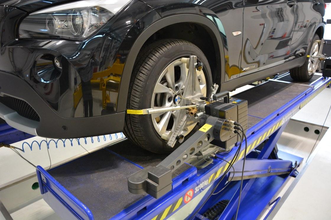
Wheel and Axle Alignment
The test stand is used to measure and adjust the wheel position of a vehicle. To meet the requirements of today’s complex multi-link axle systems, an optical process based on laser axle measurement is used for maximum accuracy. On this basis, the wheel geometry parameters that are so decisive for wear, driving dynamics, ride comfort and efficiency can be determined. These parameters are fundamental for the vehicle model.
Vehicle types: all motor vehicles up to 3.2 tons vehicle mass, both axles
Measured variables for determining the wheel position variables as well as for vehicle preparation:
– Determination of Total, single Track
– Camber
– Wheel Offset
– Axle Angle
– Caster, Caster Correction Range
– Spread, toe-out Angle, maximum Steering Angle
Detailed information can be found in the data sheet.
Vehicle Inertia Measuring Machine

The vehicle inertia measuring maschine is used to determine the center of gravity position and mass moments of inertia of motor vehicles. Both variables have a decisive influence on dynamic wheel loads and wheel load changes as well as the natural vibration behavior of a vehicle. Movements of the vehicle body can have a negative effect on driving stability. Furthermore, frequency ranges of the body vibration must be avoided, which can lead to nausea for the occupants.
The center of gravity position is calculated from the vehicle dimensions and static wheel loads. To determine the center of gravity height, one axle of the vehicle is raised. The moments of inertia about three axles are determined by swaying the vehicle.
Vehicle types: all motor vehicles up to 2.6 tons vehicle mass (wheelbase: 4.35m, track width: 1.2m, minimum ride height: 80mm).
Measurement parameters for determining the position of the center of gravity, mass and inertia properties, analysis of the influence of various loading conditions on the complete vehicle, and measurement of individual components or subsystems:
– Vehicle Mass, Center of Gravity Position
– Mass Moments of Inertia about the three Axes x, y, z
– Vehicle Position relative to the Coordinate System
The above-mentioned measured quantities are determined with the highest precision in a procedure specially developed with CFM Schiller and exceed the state of the art.
Detailed information can be found in the data sheet.
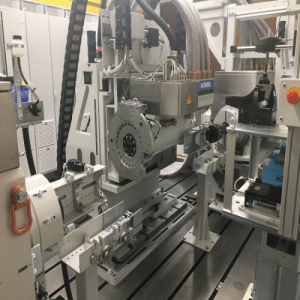
Tire Test Bench
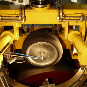
The tire test bench, designed as an external drum type, offers testing capabilities for motorcycle tires, passenger car tires and light truck tires. The two main assemblies of the external drum tire test rig are the steel drum with the drive unit and the test rig structure with the force and torque transducers of the measuring hub and the adjusting devices. The tire is pressed onto the drum by means of a centrally located rotary-lift unit with an adjustable normal force (wheel load). The test rig allows the variation of various parameters, such as speed, wheel load, slip angle, camber, direction of rotation and inflation pressure. The very stiff test rig design with natural frequencies above the primary tire vibration frequencies specifically allows highly accurate and reproducible identification of tire vibration modes.
Vehicle types: Tires of all motor vehicles (passenger cars, trucks, two-wheelers).
Measured variables for determining tire vibration behavior, operational stability and lateral force behavior:
– Forces and Moments on the Wheel in x, y and z Directions (6-Component Measuring Hub)
– Wheel Position Variables, Speed
– Tire Deflection, Tread Temperature, Inflation Pressure
The above-mentioned measured variables are determined with high precision in an external drum tire test rig.
Detailed information can be found in the data sheet.
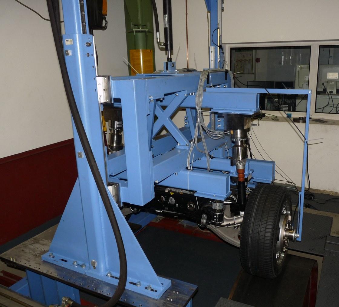
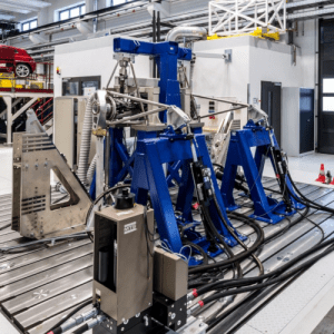
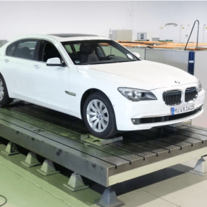
Suspension Motion Simulator

In order to meet the ever-increasing demands for complete vehicle models that are as realistic as possible and to analyze the interaction of the various vehicle components, a complete vehicle vibration test bench (Suspension Motion Simulator, SMS for short) is in use at the IAD’s “Fahrzeugtechnisches Versuchszentrum” (Test Center).
This is a servo-hydraulic test stand that allows one axle of a complete vehicle to be excited at a time on the stationary wheel up to a frequency of 30 Hz (x, y, z, steering angle). At the same time, the resulting 6-axle movements are measured at the tire slack, at the wheel hub and at the body. The forces and torques are measured at the tire slack and controlled if necessary.
Vehicle types: all motor vehicles up to 3.5 tons vehicle mass (wheelbase: 4m, track width: 1.9m)
Measured variables to determine characteristics on Kinematics and Compliance (K&C)- static and dynamic, the vibration and transmission behavior up to 30 Hz (ride comfort and driving dynamics), the replacement spring rate and friction analyses on the complete vehicle or on vehicle axles as well as the parameterization and validation of simulation models:
– All 3 Forces and 3 Moments on the Wheel Platforms of a Vehicle Axle
– Vertical Forces on the Wheels of second Vehicle Axle
– Position of Wheels, Body, movable Wheel Platforms
– Further measured Variables are possible: Over 20 analog Inputs can be freely assigned
The above-mentioned measured variables are determined with the highest precision and up to a frequency of 30Hz in the K&C test stand developed further with MTS, with or without wheel replacement system.
Detailed information can be found in the data sheet.
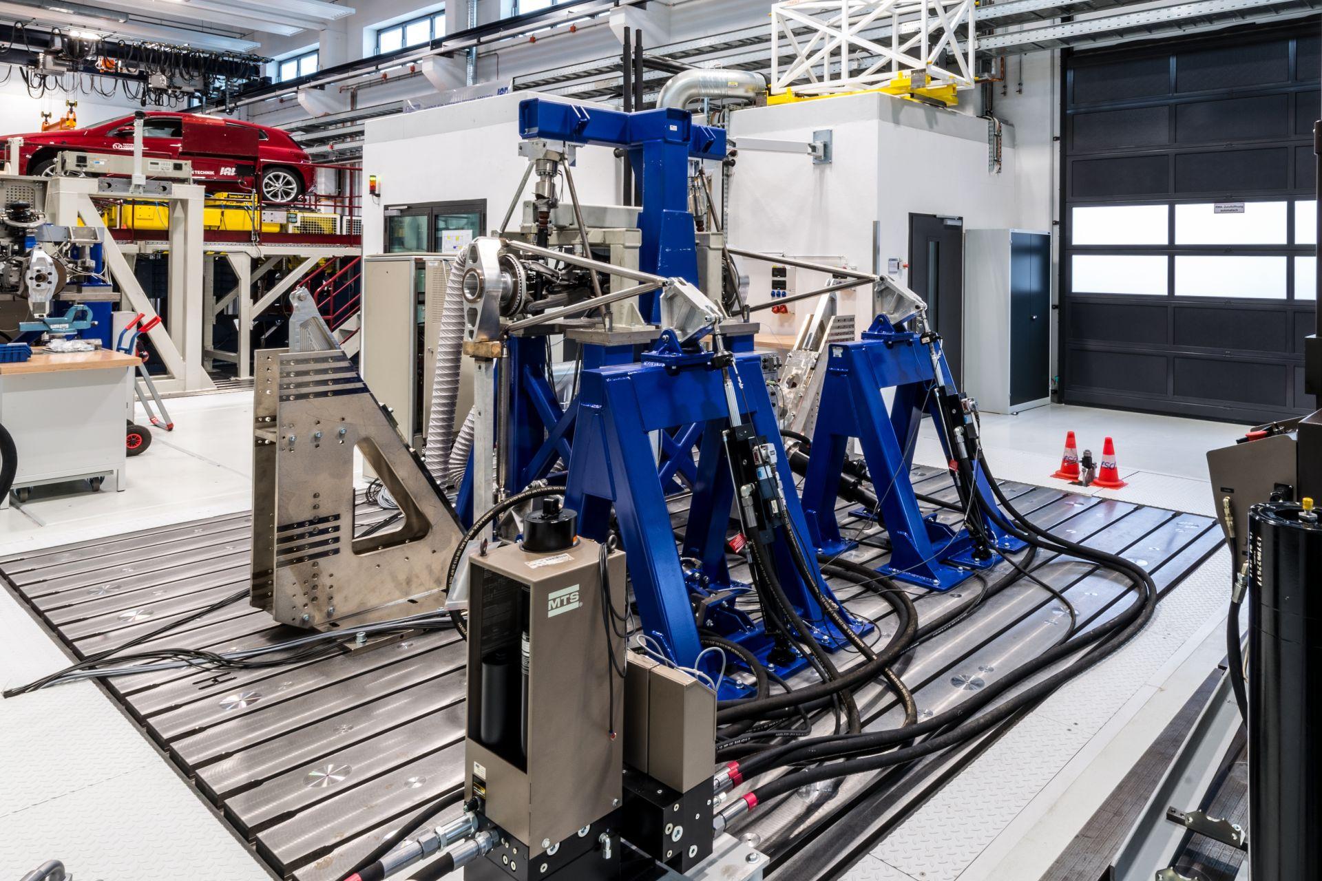
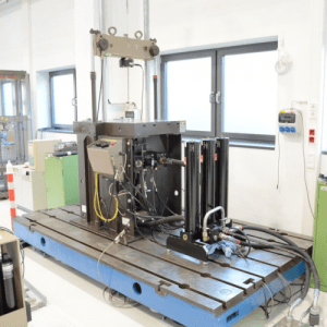
Road Load Simulator
The vehicle axle test rig was developed for vibration tests on vehicle axles. In its current state of construction, it is capable of accommodating a complete vehicle axle including body connection elements and applying loads to the wheel carriers in three spatial directions in each case. The force application points can be placed either in the center of the wheel or at the wheel contact point by means of a wheel replacement system. The load is applied via hydraulic servo cylinders. The system can be operated with displacement and conditional force control. In addition to harmonic signals up to approx. 45Hz (displacement-controlled), any signal sequences (road files) can also be displayed. Various force, displacement and acceleration transducers in several measuring ranges are available for load determination. Strain gauges can also be applied.
Vehicle types: all common motor vehicles, double wishbone, McPherson strut, space control arm, trapezoidal control arm
Measured variables for the determination of static and dynamic characteristic curves, the dynamic transmission behavior of components and complete vehicle axles as well as load data determination:
– Force: Coupling Rod Excitations left / right, 3-axle (longitudinal, transverse and vertical), Topmount left / right, 6-axle (Subframe 4 x 3-axle), upper Control Arm left / right, 3-axle (optional Extension by Strain Gauge possible)
– Displacement: Wheel Hub left /right, 3-axle (longitudinal, transverse and vertical), Topmount left /right, 1-axle (optional Extension possible)
– Acceleration: Wheel Hub left / right, 3-axle (optional Extension possible)
The above-mentioned measured variables are determined with the utmost precision in a specially developed axle hydropulser test rig.
Detailed information can be found in the data sheet.
Bremsenprüfstand
The friction technology test field comprises two flywheel mass test rigs. A wide range of vehicles can be simulated on these by varying the inertia of the flywheel masses. Various test procedures can be carried out semi-automatically.
Vehicle types: all common motor vehicles
Measured variables for the determination of friction pairings, continuous braking, emergency braking, cooling process investigation, stop braking, interval braking:
– Accelerations, Decelerations
– Vibrations
– Braking Force
– Temperature
The above-mentioned measured variables are determined using a flywheel mass dynamometer.
Detailed information can be found in the data sheet.
Wheel-Axle Test Bench
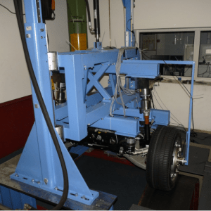
The wheel-axle test bench is used to investigate the interactions that occur in the wheel/tire/chassis system. For this purpose, the wheel is driven by a drum and the chassis is attached to its connection points on the body side. The focus of the investigations is on ride comfort and driving dynamics, whereby characteristic parameters of the respective vehicle disciplines can be determined by means of various maneuvers in conjunction with different drum surfaces.
Vehicle types: all motor vehicles and light trucks (their axles, including chassis and tires)
Measured variables for determining ride comfort (transmission behavior with harmonic excitations, blow bar crossing, stochastic excitation) and driving dynamics (steering behavior, tire behavior during extreme maneuvers, analysis of axle influence on tire behavior, driving dynamics parameters during steady-state circular driving, steering angle jump, steering angle ramp, ISO lane change, …):
– Tire Forces longitudinal, transverse, vertical
– Tire Restoring Torque
– longitudinal Speed
– Steering Wheel Angle
– Vertical Movement of the Wheel Center
– Internal Forces at all bolt-on Points of the Axle on the Chassis
– Optional: Measuring Track Rod, Characteristic Accelerations on freely oscillating Components
The above-mentioned measured variables are determined with the utmost precision using a wheel-axle test rig developed in-house.
Detailed information can be found in the data sheet.
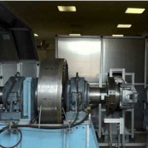
3EM-Powertrain Test Bench
The powertrain test bench at the Chair of Automotive Engineering at TU Dresden consists of three high-performance permanently excited synchronous motors, one of which serves as a substitute for the VKM (input) and the other two (wheel machines = output) to represent the driving resistances. In addition to the transmission (manual, automatic, etc.), other powertrain components (e.g., sideshafts, flywheels, clutches) can also be examined. Different configurations of the powertrain can be represented: Inline, front-transverse and front-longitudinal.
One of the distinguishing features of the test bench is that the e-machines have extremely low rotational moments of inertia, so that even very demanding tests can be performed. Here, the mapping of torque pulsations and the representation of wheel slip are examples to be mentioned.
Vehicle types: all common drives of motor vehicles (main transmissions (manual, automated, transverse and longitudinal), transfer cases, axle drives (front/rear axle), side shafts, flywheels, clutches, transmission control units (TCUs), e-axles with battery simulation (on request)
Measured variables to determine shift comfort optimization, drivetrain-excited longitudinal vibration expression, load changes (tip-in/tip-out), full-load acceleration, simulation of torque pulsation of a VKM, novel drivetrain components (e-axles, dedicated hybrid transmissions, etc.), operating strategies as well as their optimization, efficiency studies as well as of wheel slip simulation, operating load post-run tests, post-run test cycles (WLTP, FTP75, etc.):
– Speed
– Torque
– Vibrations
– Temperatures
– Further Measurement Channels are available as an Option
The above mentioned measured variables are determined highly accurately in a highly dynamic powertrain test bench specially developed with HORIBA and exceed the state of the art.
Detailed information can be found in the data sheet.
Multi-Axial Elastomer Bearing Test Bench
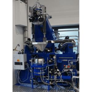
The elastomer testing and measuring machine is used for static and dynamic characteristic value determination of elastomer components. The elastomer testing machine can be used to provide a closed, independent and scientifically based supply chain for service life testing, modeling and validation of elastomeric bearings. Testing and measurements under temperature influence in the range of 20°C to 130°C are possible. The extension of a cooling system to reach measurement temperatures down to -20°C is planned.
Vehicle types: all common motor vehicles (elastomer as well as hydro bearings)
Measured variables for the determination of static characteristics as well as dynamic characteristics in X-, Y- and Z-direction, operating load post-run tests / service life tests:
Force:
– X-, Y-axis max. 25kN, Z-axis max. 50 kN, rotational axis max. 1000Nm.
Displacement:
– Static: Z-axis: 100mm (+/- 50mm), X-, Y-axis: 50mm (+/- 25mm).
– Dynamic: Translational: 1mm at 80Hz; 0.1mm at 130Hz, Rotational: +/- 30° or +/- 400 Nm at 6Hz.
Temperature Range:
– 20°C…+130°C
The above mentioned measured quantities are determined with highest accuracy in a specially developed and highly dynamic elastomer bearing test rig and exceed the state of the art.
Detailed information can be found in the data sheet.
Single-Axis Hydropulser
The single-axis hydropulser of the Department of Automotive Engineering is used to investigate static and dynamic characteristic curves on a wide variety of vehicle components. Currently, mainly shock absorber, engine mount and tire characteristics are determined. The measuring system obtains a force response by means of a sinusoidal, rectangular or ramp-like path excitation.
Vehicle types: all common motor vehicles and light trucks (shock absorbers, elastomers, hydromounts, vehicle axle components, tire samples)
Measured variables for determination of shock absorber characteristics, temperature influence on engine bearing characteristics, influence of preconditioning cycles on hydro bearing characteristics, natural frequency investigations of tires as well as temperature influence of rubber samples of tires or bearings (max. load capacity 100 kN, heat chamber up to max. 90°C for bearing measurements):
Force:
– Static: Load range: +/-50 kN (max. 100kN)
Displacement:
– Static: max. +/-125 mm
– Dynamic: 0 -100 Hz at approx. 0.5 mm displacement
The above measured variables are determined in a specially developed hydropulser test rig.
Detailed information can be found in the data sheet.
Multi-Axis Hydropulser
The multifunctional test Rig serves as an all-rounder for implementing a wide variety of testing tasks from the fields of vibration measurement technology to component testing of elastomer bearings. Different linear cylinders, hydraulic actuators as well as displacement and force measuring devices are available at this test facility.
Vehicle types: all common motor vehicles (elastomeric bearing, complete vehicle).
Measured variables to determine static and dynamic characteristics, dynamic transmission behavior of components to complete vehicles, elastomeric bearing properties, the load of any test specimens with servo cylinder:
– Force: about 30 kN
– Displacement: 250 mm
The above mentioned measured quantities are determined in a state of the art vibration test rig.
For detailed information, please refer to the data sheet.
Universal Testing Machine
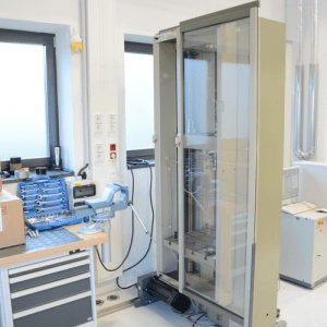
The universal testing machine from Zwick/Roell is used specifically for function testing on components or for simple materials testing. The spindle drive enables safe and slow static characteristic curves to be determined, which is particularly advantageous in prototype construction.
Vehicle types: all common motor vehicles (springs and control arms)
Measured variables for determining static spring characteristics and wishbone characteristics:
– Force: approx. 50 kN
– Displacement: 1000 mm
– Speed: 500 mm/min
The above-mentioned measured variables are determined in a state-of-the-art tension-compression test rig.
Detailed information can be found in the data sheet.